

 Share This Page
| Home | | Computer Graphics | | Adventures in Ray Tracing | | | | Share This Page |

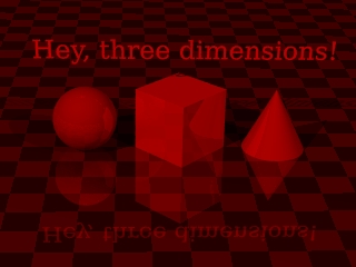
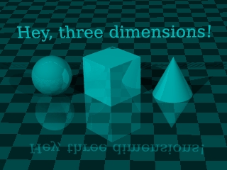
 Click this image repeatedly (
to see the process of conversion |
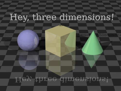
This page will teach you how to produce three-dimensional images. By "three-dimensional" I mean images with depth, not just perspective. The method used, called "anaglyphic", requires you to acquire some special glasses with red and blue lenses — they look liks this:3D Vision Theory. These glasses aren't expensive, and making 3D images can a be a lot of fun. Strictly speaking, this technique isn't included with POV-Ray. It's my extension, if you will, although not much effort is required to produce 3D images in this way.
In the real world, we perceive depth because we have two eyes. Our left eye gets a view slightly different than our right, after which our brain processes the two views, extracting depth cues. It's a remarkable system that required many millions of years of evolution to perfect. If we want to create a 3D computer display, we have to figure out how to steer two different views of the same scene to our left and right eyes — our eyes must see distinct perspectives, and for this trick to work properly, those perspectives should have roughly the same horizontal separation that our eyes do. The entire computer 3D graphics activity revolves around inventing clever ways to present separate views to our left and right eyes. The method we are discussing is called "anaglyphic," a variant on a Latin word that means "carved in low relief." For our purposes, we can feel a sense of relief that the cost is low. Basically this method relies on using two images displayed in separate colors — colors carefully chosen to be mutually exclusive, so that little or none of one color gets through the lens meant for the other color. To see if this actually works, pick up your 3D glasses and try reading the lines below using only one lens at a time:Real World ExampleBy the way ... if this experiment failed, you have the wrong kind of 3D glasses. :)
- This line should only be visible through the red (left) lens.
- This line should only be visible through the cyan (right) lens.
People have been creating anaglyphic images for a long time, using cameras instead of computer graphics programs. All that is needed are two pictures separated by a small horizontal distance, roughly equal to the distance between our eyes. Changing a camera's location is easy — you just take a picture, move the camera and take another picture. Here is a real-world example where I did just that:Virtual World ExampleThe astute reader will notice several things about these images:
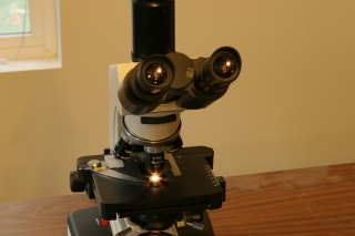
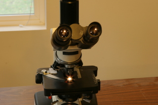
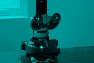
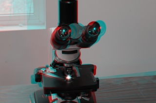
- The two original images are scarcely different, but a close look will reveal a small difference in the viewing angle.
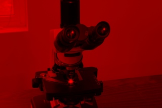
- When viewing the separate, colored images with your anaglyphic glasses, one lens at a time, you will see that one of the two images is essentially invisible. This is how the color-filter method works — by blocking out the unwanted color and only allowing the correct color to get to the viewer's eye.
- By carefully viewing the final result image one lens at a time, and in comparing this image with the two original views, you will see the two original viewing angles recreated, one per color.
- Color is sacrificed for depth. Because we need to use colors to steer the correct image to the correct eye, we must give up all the original image colors.
Okay, now for a computer example using POV-Ray:The Details
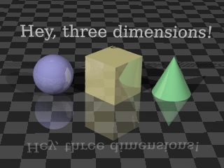
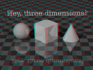
This seems rather simple, but there are some details. How do we manipulate the POV-Ray scene description file to create the two views, separated by the required distance? There are several approaches to this problem, of increasing effort and sophistication. Consider this block of code from a scene description we want to render in 3D:Well, a couple of possible approaches come to mind. Perhaps we can:camera { perspective location <0, 12, -24> sky <0, 1, 0> direction <0, 0, 1> right <1.3333, 0, 0> up <0, 1, 0> look_at <0, 0, 1> angle 24 rotate <0, 0, 0> }A similar approach using rotation looks like this:
- Change the specifier "location <0, 12, -24>" to:
- "location <-1.5, 12, -24>" in a scene copy for the left view,
- "location <+1.5, 12, -24>" in a scene copy for the right view,
- Render the separate views.
Both these approaches will work, but they both suffer from the problem that the camera is being rotated or moved from a position that will create distortions in the desired separation effect (as the reader will discover in experiments). One solution is to place the camera at y = 0, which solves the distortion problem for both these methods, but may cause other problems, some of them aesthetic. Another, more technical, solution is to perform some trigonometric calculations to change the "sky" vector in the camera description, make it more appropriate to the camera's actual position, so that the two viewpoint translations end up looking realistic. This is moving in a rather technical direction, so I will just provide a copy of a Perl script I have written that does this automatically (as well as handling all the other steps in the process), and the more technically skilled can glean the details from the script (while others can simply use the script to create anaglyphs):
- Change the specifier "rotate <0, 0, 0>" to:
- "rotate <0, +3.5, 0>" in a scene copy for the left view,
- "rotate <0, -3.5, 0>" in a scene copy for the right view,
- Render the separate views.
Remember that to function as intended this script requires a Perl interpreter as well as the ImageMagick utilities. Linux users will have little difficulty using this script — it is well-behaved and practically runs itself. A digression. At this point, why am I not providing a step-by-step procedure to download the Perl script, put it somewhere appropriate, make sure it has the right file permissions, and execute it? The reason is that a reader who already knows how to do these things is the sort of person the script is meant for. :) Moving right along, how do we create the combined red-cyan image using the original left and right color images? Linux users can use the ImageMagick utilities, as we did earlier, like this:
- Click Here to view the anaglyph generator Perl script rendered as HTML with syntax coloring.
- Click Here to download the unadorned script (remove the ".txt" suffix to use it).
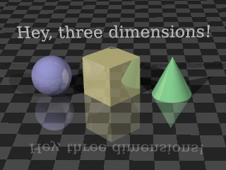
At this point, you should have your first anaglyphic image. Creating anaglyphic images obviously takes longer than simply rendering scene descriptions, therefore this activity should be deferred until you are satisfied with the normal renderings of your scene. For complex scenes and technical projects, remember that a 3D view offers information that ordinary, flat renderings cannot provide.
- Assume in this example that we have two appropriately rendered image files named "left.png" and "right.png" from the prior step.
- Remember my earlier convention with the "$" dollar-sign shell prompt? It means what follows is to be typed from a command shell, but the "$" itself is not typed.
- First, create two monochrome versions of the images (this step shouldn't actually be necessary, but there is a bug in the "composite" ImageMagick utility. It should make the images monochrome as it creates the anaglyph, but it doesn't):
$ convert -colorspace gray left.png monoleft.png $ convert -colorspace gray right.png monoright.png- Next, combine the two monochrome images into an anaglyphic image:
$ composite -stereo monoright.png monoleft.png anaglyph.png
| Home | | Computer Graphics | | Adventures in Ray Tracing | | | | Share This Page |